
Autolab Rotating cylinder electrode (RCE) complete
SKU: AUT.RCE
0,00 zloty
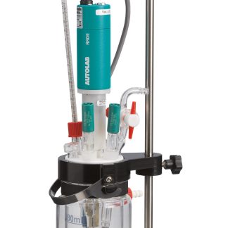
Zestaw wirującej elektrody cylindrycznej
System umożliwia realistyczne odwzorowanie warunków pracy instalacji przemysłowych, takich jak rurociągi, co czyni go idealnym narzędziem do badań korozji, analizy przepływów turbulentnych oraz wyznaczania parametrów hydrodynamicznych, takich jak liczba Reynoldsa.
Autolab RCE (Rotating Cylinder Electrode) to zaawansowana elektroda wirująca cylindryczna, zaprojektowana z myślą o precyzyjnych badaniach korozyjnych przy minimalnym poziomie szumów.
Dzięki najwyższej prędkości obrotowej spośród dostępnych komercyjnie systemów, Autolab RCE umożliwia symulację szerokiego zakresu warunków przepływu. W porównaniu do innych elektrod cylindrycznych o średnicy 12 mm, osiąga dwukrotnie wyższe prędkości obrotowe, co przekłada się na symulację nawet 50% wyższych możliwych prędkości przepływu.
Autolab RCE wyróżnia się również bardzo kompaktową konstrukcją – zajmuje zaledwie około 1/10 objętości typowych systemów tego typu, przy zachowaniu pełnej funkcjonalności.
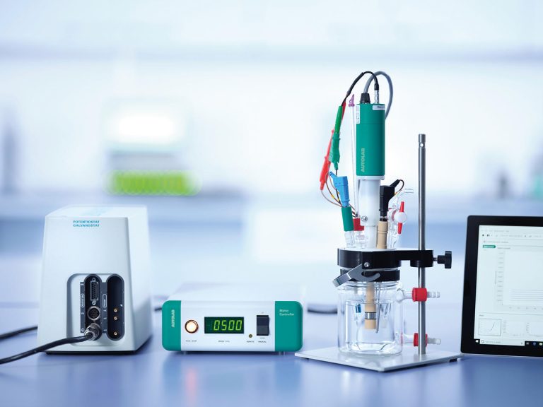
Prędkość obrotowa: 100 – 5 000 RPM (przy końcówce RCE 12 mm)
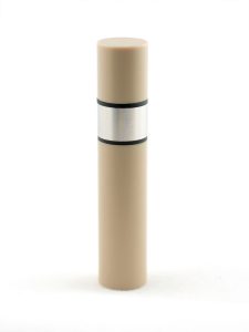
Dostępne rozmiary elektrod: 12 mm średnicy, 8mm wysokości.
Materiał elektrod: Stal węglowa (1018), Stal nierdzewna (304),
System współpracuje z końcówkami RDE: 3 mm, 5mm.
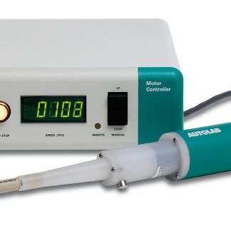
W zestawie dostarczany jest jednostka sterująca, rotator, końcówka Stal węglowa (1018), Stal nierdzewna (304),
Downloads: Manual.
Metrohm Autolab offers access to over 150 application notes describing potentiostat/galvanostat applications in various fields of electrochemical research. Below, we present an overview of the notes describing the basic techniques, as well as selected application notes for research in the areas of energy, electrocatalysis, corrosion, electrolysis, and sensors.
To view all available application notes, please visit our website Metrohm-Autolab.
Determining the parameters for analysis in the EIS technique
This application note presents the application of EIS to the characterization of a PV device, for example a dye-sensitized solar cell (DSC).
This application note presents the use of the PGSTAT302N with the FRA32M module and LED.KIT to characterize a PV device, for example a dye-sensitized solar cell (DSC) using IMVS and IMPS methods.
Methods for determining Ohmic drop values: Current interrupt and positive feedback
Testing battery properties using CV and EIS techniques and RHD mountings
Testing battery properties using constant current charge and constant potential discharge cycles using the VIONIC potentiostat and INTELLO software
Evaluation of paracetamol content by the SWV method using the VIONIC potentiostat and INTELLO software
Assessment of the presence of boundary coverings based on the ISO 17463 standard
Determination of corrosion rate in turbulent flow using the rotating cylinder method
Characterization of ion transport in redox processes using a rotating disc electrode
Investigation of I/V Properties of Fuel Cell Stacks Using Voltage Multiplier and Dynamic Load Interface
Introduction and examples of Metrohm-Autolab spectroelectrochemistry systems
Testing the properties of PV cells using the Charge extraction method
Comparison of linear and step CV results using a commercial capacitor as an example.
What is a three-electrode system? When to use a four-electrode system? 

The three-electrode system is the most commonly used configuration in electrochemistry. This system uses three electrodes: a working electrode (WE, working electrode), reference electrode (RE, reference electrode) and an auxiliary electrode, also called a counter-electrode (CE, counter/auxiliary electrode).
During an electrochemical measurement, current flows between the working electrode (WE) and the counter electrode (CE). The potential difference is controlled between WE and CE, while precise potential measurement is performed between the working electrode (WE+S) and the reference electrode (RE).
In a three-electrode system, the measuring clamp S (sense) is connected to the working electrode (WE), so that the potential of WE relative to RE can be accurately measured and/or controlled.
The four-electrode system is used in applications where it is necessary to precisely measure the potential difference (measured between the reference electrode RE and the measuring electrode S), which is created as a result of current flowing through a precisely defined phase boundary - between the working electrode (WE) and the counter-electrode (CE).
This type of configuration is not commonly used in classical electrochemistry. It is most often used to study ion transport across membranes or two-phase systems of immiscible liquids.
This system enables the determination of interfacial resistance or membrane conductivity by separating the current path (WE–CE) from the potential measurement path (RE–S), which minimizes the influence of ohmic drops on the measurement result.
What are reference and auxiliary electrodes (RE and CE)?
Reference electrode (RE, reference electrode) is an electrode with a stable and well-defined potential against which the potential of the working electrode (WE) is measured.
Its main function is to act as a reliable and repeatable potential reference point in an electrochemical system, enabling accurate measurement of the working electrode potential.
W hereby The study lists the most commonly used reference electrodes and their scope of applications.
Auxiliary electrode (CE, counter/auxiliary electrode) is designed to "collect" current in an electrochemical system. To ensure the potential stability of the reference electrode (RE), no current should flow through it. Due to the electrometer's very high input impedance, current in the system flows only between the working electrode (WE) and the auxiliary electrode (CE).
It is important that the auxiliary electrode is made of an electrochemically inert material so that it does not generate by-products that could disrupt the system being tested.
Additionally, the surface of the auxiliary electrode should be larger than the surface of the working electrode, which helps to limit its polarization and ensure the correct measurement process.
Is the lowest current range the same as the lowest measurable current? What about current resolution?
The lowest current range on the device represents a setting optimized for measuring very low currents (high sensitivity), while the actual lowest measurable current can be several orders of magnitude lower – and is limited by factors such as noise, electrochemical system properties, measurement conditions, cabling, etc.
Current resolution, in turn, is determined by the number of bits in the analog-to-digital converter (ADC) and the selected current range. It defines the smallest current change that the instrument can resolve, but it does not indicate the smallest current that can be reliably detected.
To achieve the best measurement quality, select the lowest possible current range that does not overdrive the signal—this maximizes resolution. However, it's important to remember that the actual detection threshold in practice is most often determined by noise and the limitations of the entire measurement system, not just the nominal range or resolution of the equipment.
What is open circuit potential (OCP)?
Open Circuit Potential (OCP, open-circuit potential) is the potential of the working electrode (WE) relative to the reference electrode (RE) in the absence of current flow through the system (i.e., with an open circuit). The open-circuit potential (OCP) is of great importance in electrochemical studies because it constitutes a reference point — the resting potential of the system, measured without disturbing it by applying current or potential.
OCP corresponds to the equilibrium potential at the electrode-electrolyte interface, where the rates of oxidation and reduction reactions at the electrode surface are equal. As a result, there is no net current flow, although electrochemical processes continue to occur in both directions. This is a good indicator of the equilibrium state in an electrochemical cell. OCP is a key parameter in assessing the thermodynamic stability of materials, analyzing their corrosion behavior, and monitoring changes occurring on the electrode surface.
Additionally, it serves as a reference point for other electrochemical techniques, such as electrochemical impedance spectroscopy (EIS) or corrosion measurements.
Does the rise time of the potentiostat matter for experiments?
The rise time of a potentiostat is defined as the time interval required for the output signal to increase from 10% to its final amplitude of 90%. This parameter is particularly important in experiments involving very fast electrochemical phenomena.
Reliable measurement of such fast processes is only possible if the time constant of the electrochemical system is shorter than the analyzed time intervals.
What is the length of the measuring cables? Can longer cables be used?
For all Metrohm Autolab potentiostats, the standard measuring cable length is 1.5 m. Device specifications are tested and guaranteed only using cables of this length.
However, it is possible to order and use longer cables. To do this, please contact us.
What is the difference between maximum voltage and applied voltage?
Compliance voltage: refers to the maximum voltage that the potentiostat's internal circuitry can deliver to the auxiliary electrode (CE) to achieve and maintain a given voltage at the working electrode (WE) relative to the reference electrode (RE). This can be considered the device's limit. If the electrochemical system's resistance or the experimental requirements require a higher voltage than the potentiostat's limit, the device reports an "overload," meaning it cannot maintain the set potential. A higher value of this parameter provides greater flexibility, so advanced models—such as the VIONIC (±50 V)—are better suited for high-resistance or more demanding electrochemical systems.
Applied voltage / potential: This is the user-set voltage that the potentiostat should maintain or scan at the working electrode (WE) relative to the reference electrode (RE). It is therefore a given experimental condition that forces an electrochemical reaction to proceed or enables its measurement.
What is the difference between a potentiostat and a galvanostat?
The key difference between a potentiostat and a galvanostat is what is being controlled during measurement:
- Potentiostat controls voltage and measures current.
- Galvanostat controls current and measures voltage.
Both devices are commonly used in electrochemical experiments, and the mode chosen depends on whether a constant potential (potentiostat) or constant current (galvanostat) is required. All Metrohm Autolab instruments offer both modes of operation, providing flexibility for a variety of electrochemical applications.
Potentiostatic mode is typically used when:
- the system impedance is high,
- it is required to scan the potential in a specific range (e.g. in cyclic voltammetry),
- the aim is to study reaction mechanisms, redox potentials or electrochemical kinetics,
- the current response to a controlled potential is analyzed (e.g. in diffusion studies or Tafel analysis).
Galvanostatic mode is typically used when:
- the system impedance is low (e.g. testing batteries and cells),
- it is required to maintain a constant current, e.g. in an electrolyte or during electrochemical deposition.
What types of temperature sensors are compatible with Metrohm Autolab potentiostats?
The VIONIC potentiostat will handle any K-type thermocouple.
In Autolab AUT302N, AUT204 potentiostats and in M101/M204 multi-channel systems, the PX1000 module is required to support Metrohm Pt1000 sensors.
For more information, please contact us.
What is the difference between Cell-Off and Cell-Isolated?
In a state Cell-Off the electrochemical system is switched off in the sense that no current flows between the auxiliary electrode (CE) and the working electrode (WE), but the potential is still measured between the reference electrode (RE) and the measuring terminal (S).
In case of Cell-Isolated There is no electrical connection between the electrochemical system and the VIONIC potentiostat electronics. This condition can occur due to the system's protection tripping or the device entering an error state. In this state, no current or potential values are transmitted to the potentiostat.
For detailed information, please refer to the user manual. INTELLO and VIONIC.
When is it necessary to use the floating mode of the potentiostat?
When any part of the electrochemical system (including the measuring cell or electrolyte) is connected to ground (earth), electrochemical measurements may only be made using a potentiostat/galvanostat with floating electronics.
Otherwise, it is recommended to use non-floating mode for optimal measurement performance.
VIONIC is equipped with the ability to select floating operation mode in 3 grounding variants.
How are Metrohm Autolab RDE, RRDE and RCE systems controlled?
Metrohm Autolab rotators used in RDE, RRDE, and RCE experiments are controlled and fully integrated with both INTELLO and NOVA software. They also offer single-speed manual control.
Hydrodynamic data analysis is available in NOVA and can be used for both INTELLO and NOVA measurements.
What is the warranty and support period for Autolab instruments?
All Metrohm Autolab instruments come with a 3-year warranty.
Instruments and software will be supported for at least 10 years after the end of production of a given model.
How to analyze electrochemical impedance spectroscopy (EIS) data?
What is the difference between a potentiostat/galvanostat and an electrochemical impedance analyzer?
A potentiostat/galvanostat is a precision device used to control and measure electrical parameters—potential and current—in an electrochemical system. It is a fundamental tool for conducting electrochemical experiments such as cyclic voltammetry, chronoamperometry, and chronopotentiometry, providing precise control of the applied potential or current.
An electrochemical impedance analyzer is a specialized add-on module, often integrated with a potentiostat/galvanostat. It allows for the application of AC signals over a wide frequency range and measurement of the impedance of an electrochemical system. This technique, known as electrochemical impedance spectroscopy (EIS), provides detailed frequency-dependent information about electrochemical processes.
EIS data allow the description of electrochemical systems by providing information on processes occurring at the electrode-electrolyte interface, such as charge transfer, diffusion, double layer charging, adsorption, and other parallel or sequential phenomena.
How to choose the appropriate frequency range in an EIS experiment?
What are the key requirements for correct EIS measurement?
For an electrochemical impedance spectroscopy (EIS) measurement to be correct and interpretable within the framework of impedance theory, the following basic conditions must be met:
Linearity: The electrochemical system must respond linearly to an applied AC signal. This means that doubling the input signal amplitude should result in a proportional (doubling) increase in response, without the creation of harmonics—the response should consist solely of the fundamental frequency component.
Constancy over time: The system must remain in a steady state throughout the measurement. Its basic properties (e.g., surface condition, concentration profiles, layer thickness, temperature) should not change.
Causality: the system response must be directly induced by the applied AC excitation, without the influence of external disturbances disturbing the input-output relationship.
Finiteness: The real and imaginary parts of the impedance must assume finite values over the entire frequency range under consideration. This means that at very high and very low frequencies, the impedance tends to limit values or predictable behavior.
Can EIS measurements be made above 1 MHz?
Yes. EIS measurements above 1 MHz require the use of special equipment (VIONIC or ECI10M module) and specially designed measurement cables.
EIS measurements above 1 MHz can be performed in potentiostatic mode.
Is VIONIC a network instrument?
Yes, the VIONIC can be connected both to a network and directly to a computer. The number of connected VIONIC devices depends on the capacity and performance parameters of the given network. Each VIONIC potentiostat has a factory-programmed IP address, but this can be changed to suit the network's requirements.
Measurements can be performed simultaneously on multiple VIONIC instruments using a single computer running INTELLO software.
The number of instruments connected in this way depends on the performance of the network and computer.
It is recommended to contact your IT department to prepare the appropriate network settings to connect VIONIC to the network.
What is the size of the VIONIC's built-in memory?
The VIONIC's built-in memory can store up to 10 million data points, depending on the type of measurement being performed.
If the computer is disconnected from VIONIC during an experiment, the INTELLO software informs the user how long the measurement can continue without a connection to the computer.
Is INTELLO compatible with NOVA?
INTELLO is the new control and data acquisition software for VIONIC potentiostats. NOVA is the control and data acquisition software used in the AUT302N, AUT204, AUT101, Autolab IMP systems, and the M101/M204 multi-channel potentiostats.
The two software packages are not compatible with each other, however, data measured in INTELLO can be directly exported to NOVA if necessary.
Does INTELLO include standard procedures ready to use?
Yes. INTELLO includes a complete library of default procedures covering all electrochemical techniques. These procedures are ready to use and can be edited, allowing you to save modified procedures.
INTELLO allows both routine and exploratory work: you can use basic parameters by changing only selected values, as well as edit measurement sequences using advanced commands such as repetition loops, automatic data export and other functions.
Editing procedures allows you to save and copy their fragments, but it is not possible to transfer them between INTELLO and NOVA programs.